Recently I participated in a GameJam. One of the requirements of the GameJam was to recreate the graphics of an old game, so we chose to recreate the graphics of the PS1 era. The first thing that comes to mind when talking about the PS1 era is, of course, the pitifully small number of polygons and the low resolution.
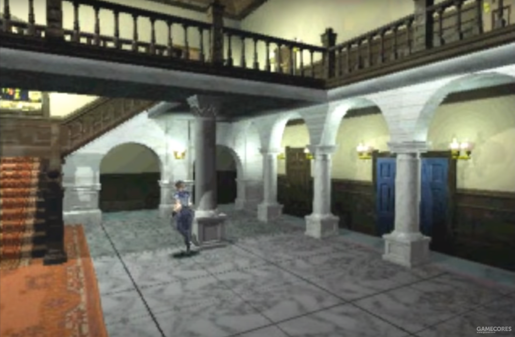
But it’s very easy to do all of this, adjust the screen resolution a bit and make it a bit rougher when modeling. Lower the resolution of the mapping a bit, and you can do it. What I mainly want to discuss today are two easily overlooked products that are unique to that era.
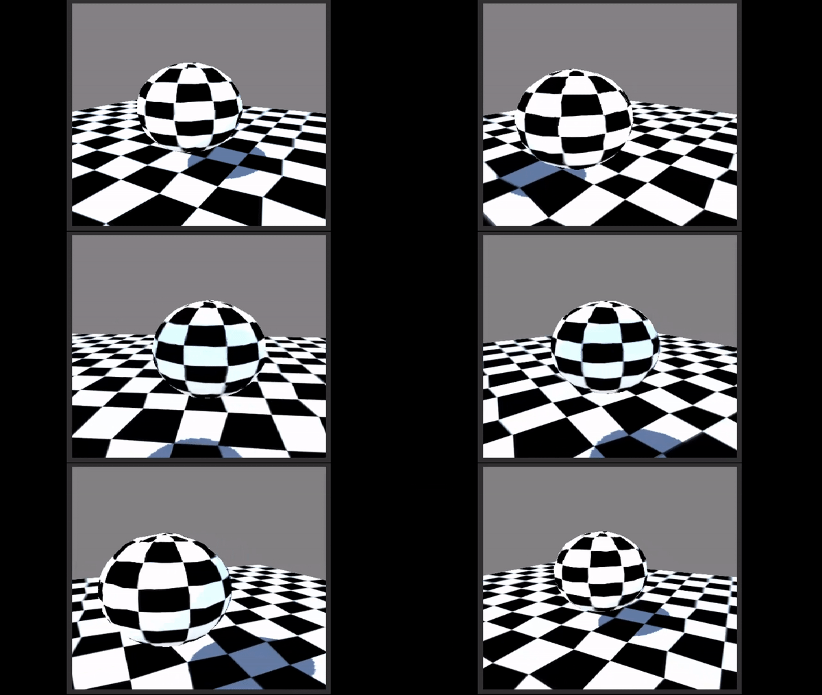
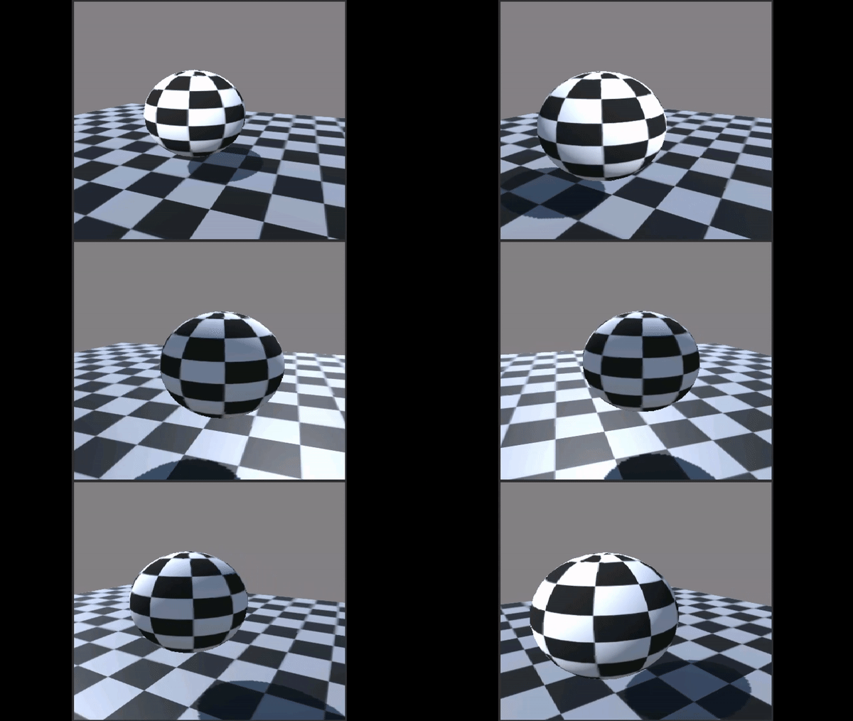
Compare the two GIFs below and you might see the problem. (Please ignore the difference in lighting, both images use the same model, same mapping and same resolution. The only difference is the rendering method)
So let’s take a look at what was wrong with the PS1 era graphics and why it had those problems.
I. Model jitter
Look closely at the surface of the sphere and you get the impression that the surface of the sphere seems to be deforming all the time.
The PS1’s CPU, which used a CPU called the R3051, utilized an R3000A architecture that most people these days have never heard of. This architecture originally supported four unique coprocessors, which could also be interpreted as supporting an optional four function modules. But as a gaming console that needs to save money, you can’t get a full load of them. So the PS1 only has two.
One of the two co-processors that Dafa did not install is the floating point computing acceleration unit. In human terms, it’s a functional module that makes the CPU calculate numbers with decimals a little bit faster. Not installing this module causes the PS1 to minimize the number of numbers with decimals, otherwise the calculations are very slow. When drawing the model, the need for decimal calculation is very large, if you can draw the model on this step to eliminate the decimal point, then you can save a lot of performance.
This will give you an idea of how a model is rendered to the screen. It will also help you understand how model jitter is generated. First of all, the model contains only vertex information, i.e. information about the position of the vertices of a polygon and which vertices they are connected to. The game then needs to convert the vertices in the model, one by one, from coordinates in a three-dimensional space to coordinates on a two-dimensional screen.
Where Dafa steals the show is in this coordinate conversion. Coordinate conversion is divided into five steps, I will not expand here to write the specific five steps, interested in point here. PS1 in the last step of the coordinate conversion, the decimal part of the coordinate information is discarded.
Imagine, to make the movement of an object look smooth, then the higher the precision of the object’s coordinates, naturally the smoother the object moves, and the more representative of its real position you see it in. So if you ignore all the numbers after the decimal point, naturally the object’s movement becomes very jumpy and not representative of its true position.
II. Perspective errors in mapping
Looking closely at the ground under the sphere, you can see that the ground mapping creates a certain amount of distortion. And this distortion changes depending on the angle at which you look at the ground.
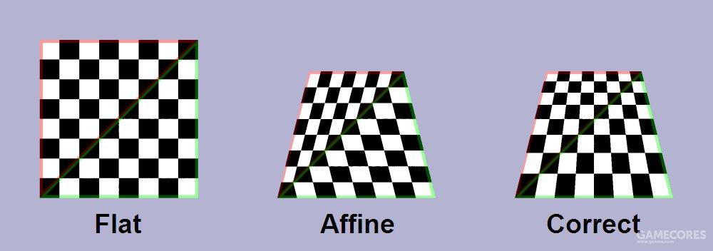
It can be noticed by looking at the picture above that a plane, when viewed from an oblique angle. The mapping on the plane without perspective correction appears to be clearly wrong. This is because the texture has been applied to the plane in the wrong way.
According to our general idea, how a game model’s texture is applied to the model should of course be determined by the model itself. For example, we make a character model, and the character model has a badge on the chest of its clothes. That badge should be in that position, it shouldn’t go anywhere else. But the fact is, how to put the decal on the model correctly is a slightly complicated mathematical calculation process.
And PS1 used a wrong method in this math calculation process. I don’t know if it was because of the limitations of the machine’s performance, in order to save even a little bit of calculation, or because of the limitations of the technology, there was no way to realize the calculation of the correct placement of the maps, or maybe it wasn’t taken into consideration at the time. But, the problem just arose.
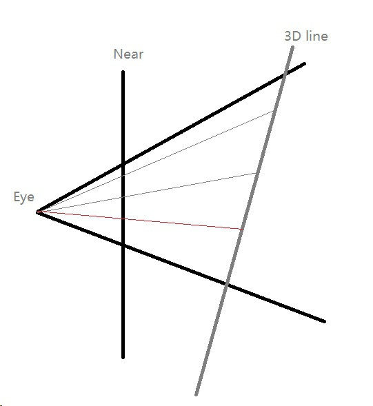
In the image above, Eye is our eye, Near is the screen, and the 3D line is a plane to which we want to apply a texture. Generally speaking, we calculate the position of the mapping, of course, based on the vertex data of the model. But in PS1, he calculated it based on the position of the screen. This is very counter-intuitive to our intuition, but that’s how PS1 calculates it, which leads to the problem that PS1’s texture maps will be distorted.
Beginning of reproduction
Knowing what the principle that creates the problem is, then we’re good to go. Let’s start trying to reproduce the effect in Unity (download of the Shader file is available at the end of the article).
First we will reproduce the model’s jitter, we will use a more flexible approach here, instead of removing the decimals in the last step of the coordinate transformation, we will do a process in the step of transforming the coordinates to the camera (step three).

This is the core code for our conversion. We use Unity’s mul function to convert the vertex coordinates directly to camera position coordinates, and then we do a really amazing thing: we multiply the vertex coordinates by a number, round off the decimals, and then divide the vertex coordinates by the number we just multiplied.
That is to say, if the original coordinate is 123.456, we multiply this number by 100 and it becomes 12345.6; we round off the decimals and it becomes 12345; and we divide it by one hundred and it becomes 123.45. In this way, we realize that we are rounding off some of the decimals. What is the benefit of doing this? Is that we can arbitrarily adjust the degree of model jitter, we want to keep how many decimal places to keep how many decimal places. This way we can both make the special effects very exaggerated like this:
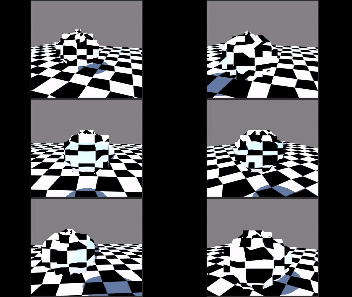
It can also be made to behave very inconspicuously
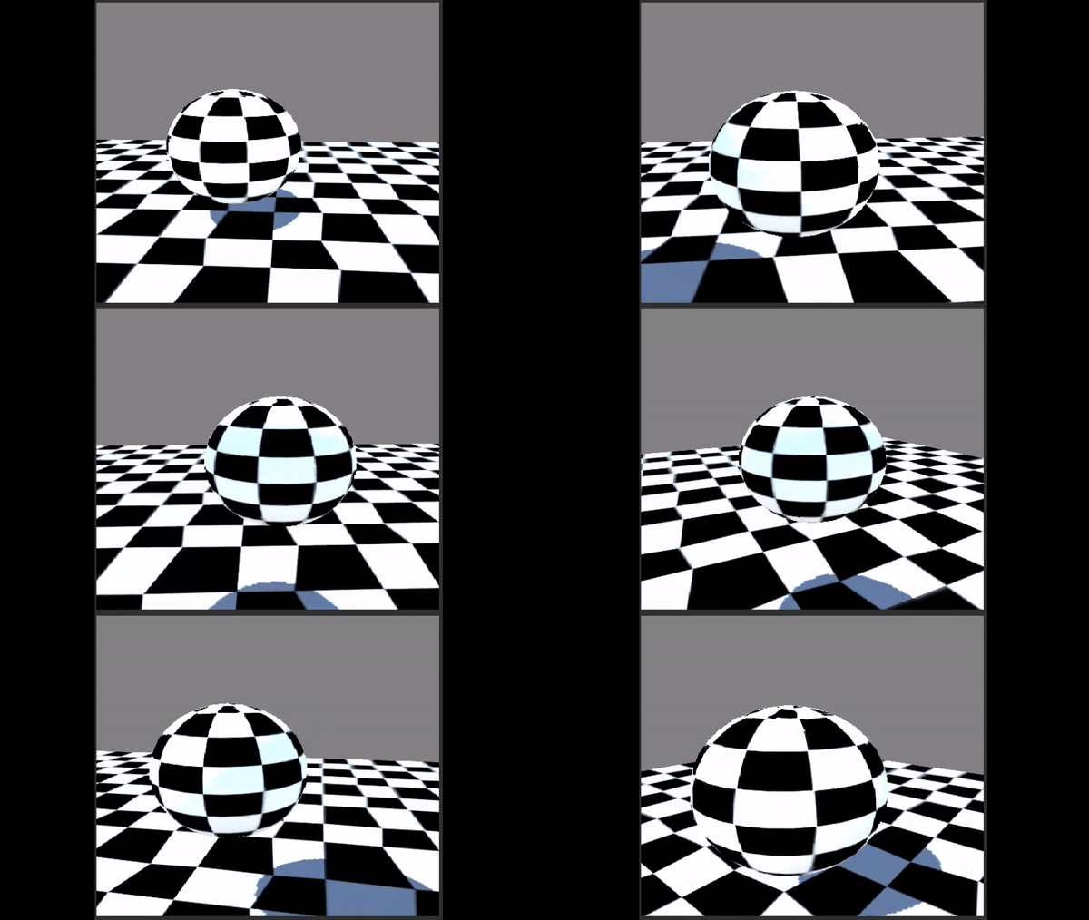
Once we’ve eliminated the decimals, don’t forget that we’re only on step three.

Once again, we utilize mul to convert the vp obtained in the previous step to screen coordinates (step five).
We then proceeded to recover the perspective error.

In this step, we will use TRANDORM_TEX to convert the texture to a texture coordinate system that matches the model. Then we directly bring the sp we got in the previous step into our mapping coordinate system calculation process, here and PS1 is the same principle. Directly using the screen to calculate the mapping.

We then remove the xy of the texture from its own z in the fragment shader so that we can get the texture to fit correctly on the object.
So, at this point, we’ve successfully replicated the effect of both models.
But we’re utilizing a vertex/fragment shader instead of the surface provided by unity, so I’ll need to program some shadows, diffuse reflections, and ambient light effects of my own.
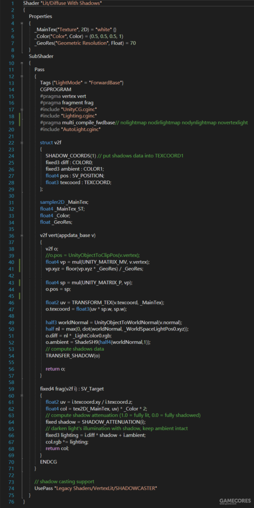
The code looks like this after adding the effect.
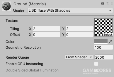
We can adjust the Geometric Resolution in the Material panel to achieve different levels of model jitter.
Github Page: https://github.com/ShenKSPZ/PS1_Graphic
Reference:
冯乐乐. (2016). 2.1.2 什么是渲染流水线. Unity Shader 入门精要 (pp. 9-18). 北京, 中国: 人民邮电出版社.
Gt小新. (2019, 十月 25). 初代PlayStation处理性能解析. Retrieved October 10, 2020, from https://www.bilibili.com/video/BV1VE41117AJ
-兮. (2018, 十一月 30). Unity: Shader Lab语法基础 坐标系转换 顶点片元着色器 语义修饰 Cg. Retrieved October 10, 2020, from https://blog.csdn.net/qq_33373173/article/details/84286717
Wikipedia. (2020, 九月 28). Texture mapping. Retrieved October 10, 2020, from https://en.wikipedia.org/wiki/Texture_mapping
知乎用户. (2016, 二月 26). 3D 图形光栅化的透视校正问题. Retrieved October 10, 2020, from https://www.zhihu.com/question/40624282
Unity Technology. (2020). Vertex and fragment shader examples. Retrieved October 10, 2020, from https://docs.unity3d.com/Manual/SL-VertexFragmentShaderExamples.html
Comments are closed